
Passive Fit in Full Arch Implants: 7 Proven Clinical Rules by Dr. Ali Cem Ulubey
In contemporary implant prosthodontics, achieving passive fit in full arch implants represents the primary mechanical safeguard against biological and prosthetic failure. When full-arch frameworks are torqued down with unresolved dimensional discrepancies, the resulting static strain is transferred directly into the peri-implant alveolar bone.
Whether restoring an edentulous jaw through an All-on-4 or All-on-6 surgical approach, framework misfit compromises the screw joint and endangers crestal bone stability. This clinical article details the 7 key clinical rules we follow at Ulubey Dental Clinic in Antalya to achieve clinically acceptable full-arch passivity by combining stereophotogrammetry (Tupel 3D) and high-density intraoral surface scanning (Dentsply Sirona Primescan Connect).
Quantitative benchmarks for passive fit in full arch implants based on established prosthodontic literature and our routine clinical protocol in Antalya:
- Rule 1: Understand Bone Rigidity vs. Periodontal Resilience
- Rule 2: Control Hooke’s Law & Avoid Cortical Overload
- Rule 3: Recognize the Limits of Surface-Only Optical Scanners
- Rule 4: Deploy Photogrammetry for Cross-Arch Vector Capture
- Rule 5: Combine Photogrammetry with High-Definition Soft-Tissue Scans
- Rule 6: Validate Every Framework via the Sheffield 1-Screw Test
- Rule 7: Account for the 10-Minute Screw Settling Effect
- Clinical FAQ & Patient Information
- Peer-Reviewed Literature References

Rule 1: Understand Bone Rigidity vs. Periodontal Resilience
Natural teeth are suspended by the periodontal ligament (PDL), a viscoelastic collagen network capable of 25–30 µm of axial displacement and up to 50–100 µm of lateral mobility (Jemt, 1991). This allows natural teeth to adapt dynamically to minor restorative inaccuracies.
An osseointegrated dental implant lacks a PDL entirely, exhibiting direct ankylotic bone-to-titanium contact with an elastic deformation threshold of under 3 to 5 µm. Consequently, achieving passive fit in full arch implants is far more critical than in tooth-supported prosthetics. Any spatial discrepancy in the framework cannot be absorbed by the implant; it is transmitted directly to the surrounding cortical bone plate.
Rule 2: Control Hooke’s Law & Avoid Pathological Bone Strain
According to Hooke’s Law, mechanical stress (σ) within a solid structure is directly proportional to strain (ε) multiplied by the modulus of elasticity (E):
• σ (Stress): Force distributed over the peri-implant cortical area (MPa).
• E (Modulus of Elasticity): Cortical bone (~12 to 18 GPa), Titanium (~110 GPa), Monolithic Zirconia (~210 GPa).
• ΔL / L (Strain, ε): Spatial framework discrepancy divided by cross-arch inter-implant span length.
Under the Frost Mechanostat Hypothesis, biological bone adaptation depends on strain levels:
- Physiological Window (50–1,500 με): Intermittent chewing forces stimulate healthy osteoblastic remodeling.
- Pathological Overload Window (> 3,000–4,000 με): Sustained static strain from an ill-fitting prosthesis produces constant micro-damage, localized ischemia, and osteoclast-mediated marginal bone resorption.
Rule 3: Recognize the Limits of Surface-Only Optical Scanners on Edentulous Arches
Intraoral scanners (IOS) deliver remarkable precision for single crowns, quadrant restorations, and porcelain veneers. However, the systematic review by Papaspyridakos et al. (2014) called for further accuracy studies on digital implant impressions, and scanning an edentulous jaw with surface scanners alone can introduce cumulative stitching drift.
An intraoral scanner captures sequential 3D surface patches, aligning them using recognizable geometric landmarks. On an edentulous mucosal ridge, where smooth tissue offers few distinct landmarks, minor angular errors compound as the scanner traverses the arch. Across a 40–50 mm inter-implant span, cumulative stitching error frequently ranges between 50 µm and over 100 µm, challenging the goal of passive seating when used as the sole measurement modality.
Rule 4: Deploy Photogrammetry for Cross-Arch Vector Capture
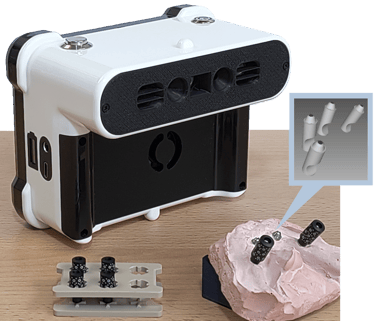
Dental stereophotogrammetry uses high-contrast geometric targets secured to multi-unit abutments (MUAs). Synchronized stereo sensors measure the 3D position and spatial vectors of all implants simultaneously, relying on coordinate triangulation rather than video surface stitching.
| Impression Modality | Physical Mechanism | Reported Literature Trueness | Clinical Considerations |
|---|---|---|---|
| Splinted Open-Tray (Analog) | Elastomeric polyether pick-up with sectioned & re-splinted acrylic resin. | 50 – 150 µm | Time-intensive; subject to impression material shrinkage and plaster expansion. |
| Surface Intraoral Scanners (IOS alone) | Continuous optical stitching across edentulous mucosal landmarks. | 50 – 100+ µm | Excellent for dentate arches; susceptible to cumulative stitching drift in edentulous jaws. |
| Stereophotogrammetry (e.g. Tupel 3D) | Simultaneous optical triangulation of multi-camera target arrays. | ~20 – 30 µm | Captures rigid implant vectors rapidly; unaffected by mucosal flexure or saliva. |
Published literature evaluating dental photogrammetry systems (including systems like PIC Dental, iCam4D, and Tupel 3D) indicates consistent trueness clustered within clinically manageable boundaries (Gómez-Polo et al., 2023).
Rule 5: Combine Photogrammetry with High-Definition Soft-Tissue Scans
A frequent clinical misunderstanding is assuming that photogrammetry replaces intraoral scanners entirely. Photogrammetry captures only implant coordinates; it cannot capture the gingival architecture, emergence profile, or palatal soft tissues.
In our clinical practice at Ulubey Dental Clinic in Antalya, Dr. Ali Cem Ulubey combines both systems:
1. Coordinate Layer (Tupel 3D): Coded scan bodies mounted on multi-unit abutments record precise XYZ vectors and angulations without stitching distortion.
2. Soft-Tissue Layer (Primescan Connect): With targets removed, our Dentsply Sirona Primescan Connect records the uncompressed mucosa, transition zone, and opposing occlusion.
3. CAD Integration: Both datasets are aligned in exocad. The framework seating cylinders are indexed strictly to the photogrammetry coordinates, while the pontic emergence profile is contoured to the Primescan soft-tissue scan, achieving both mechanical passivity and cleanable soft-tissue contours.
Rule 6: Validate Every Framework via the Sheffield 1-Screw Test
Regardless of the digital impression technology employed, objective chairside verification of passive fit in full arch implants remains mandatory before definitive delivery. The clinical gold standard is the Sheffield One-Screw Test:
-
Unilateral Terminal Seating
The framework is placed onto the multi-unit abutments. A single retaining screw is inserted into one terminal posterior abutment and tightened lightly to 10 Ncm.
-
Contralateral Micro-Gap Inspection
Under surgical loupes (4.5x), the opposite terminal abutment is inspected. If tightening one side causes the contralateral cylinder to lift or creates an opening observable clinically or with a fine probe, the framework lacks passivity.
-
Reciprocal Validation
The screw is removed and transferred to the contralateral terminal abutment, tightening to 10 Ncm to inspect the opposite side. An acceptable framework demonstrates zero fulcrum rocking in either direction.
-
Radiographic Verification
Parallel periapical radiographs are obtained perpendicular to the cylinder-abutment junction to confirm complete circumferential seating before final torquing.
Rule 7: Account for the 10-Minute Screw Settling Effect
When a prosthetic screw is tightened, applied torque is converted into axial clamping tension, termed Preload (Fₚ):
• F_p: Generated clamping preload force (Newtons).
• T: Applied tightening torque (Ncm).
• K: Torque coefficient / friction factor (~0.20 for dry titanium).
• d: Nominal diameter of the screw shank (mm).
Microscopic surface asperities on newly machined titanium threads compress and flatten when initially torqued. This physical phenomenon, known as the Settling Effect, typically causes a 10% to 18% loss of initial preload within the first 10 to 15 minutes.
If a framework does not exhibit true passivity, this initial loss of preload leaves the screw joint vulnerable to rapid loosening under cyclic masticatory forces on monolithic zirconia restorations. Our clinical protocol includes an initial torquing to 15 Ncm, a mandatory 10-minute waiting interval, and a final re-torquing pass before sealing screw access chimneys with PTFE and composite.
Clinical FAQ & Patient Information
Peer-Reviewed Clinical Literature Citations
- Branemark, P. I. (1983). Osseointegration and its experimental background. Journal of Prosthetic Dentistry, 50(3), 399–410.
- Jemt, T. (1991). Failures and complications in 391 consecutively inserted fixed prostheses supported by Branemark implants in edentulous jaws. Int J Oral Maxillofac Implants, 6(3), 270–276.
- Frost, H. M. (2003). Bone’s mechanostat: a 2003 update. Anat Rec A Discov Mol Cell Evol Biol, 275(2), 1081–1101.
- Sahin, S., & Cehreli, M. C. (2001). The significance of passive framework fit in implant prosthodontics: current status. Implant Dentistry, 10(2), 85–92.
- Papaspyridakos, P., et al. (2014). Accuracy of implant impressions for partially and completely edentulous patients: a systematic review. Int J Oral Maxillofac Implants, 29(4), 836–845.
- Revilla-León, M., et al. (2021). Comparison of conventional, photogrammetry, and intraoral scanning accuracy of complete-arch implant impression procedures evaluated with a coordinate measuring machine. Journal of Prosthetic Dentistry, 125(3), 470–478.
- Gómez-Polo, M., et al. (2023). Accuracy, scanning time, and patient satisfaction of stereophotogrammetry systems for acquiring 3D dental implant positions: a systematic review. Journal of Prosthodontics, 32(S2), 208–224.
- Bickford, J. H. (2007). Introduction to the Design and Behavior of Bolted Joints: Non-Gasketed Joints (4th ed.). CRC Press.
- Martin, W. C., et al. (2001). Implant abutment screw rotations and preloads for four different screw materials and surfaces. Journal of Prosthetic Dentistry, 86(1), 24–32.
Last updated: · Editor contact: [email protected] · ulubeydental.com/contact-us